Final Report 1 Abstract
Development of Deep-sea Geomagnetic and Electric Field
Observation
System and Its Deployment at the Okinawa Site
T. Nakatsuka, T. Miyazaki, Y. Murakami, Y. Ogawa, and
K. Nishimura
(Geological Survey of Japan)
Deep-sea geomagnetic and electric field observation system for VENUS project was developed at the Geological Survey of Japan. The system consists of a proton precession magnetometer, 3-axis ring-core fluxgate magnetometer with 2-component tilt-meter, and 2-component horizontal electric field meter using 3 electrodes. It was designed for least power consumption because the power supplied from cable system is quite limited. The equipment was manufactured step-by-step from 1995 to 1997.
We had twice chances to test and confirm valid operation of equipment at a dry dock test site, before the deployment at the deep-sea real site. Although our system operated normally from the beginning of dock test, the stainless steel frame of the equipment was proven to affect magnetic measurement. Then the arrangement of sensor to attach to the frame was improved to minimize such effect.
Our equipment was landed to the sea-bottom at Okinawa observation site in the "Kaiyo" KY99-07 cruise (Sept., 1999) in use of a deep-tow camera system equipped to the vessel. Then, the deployment of electrodes, stretching the interconnecting cable toward the branching unit and the connector interconnection were operated by the ROV "Kaiko" in the "Kairei" KR99-09 cruise (Sept.-Oct., 1999). Soon after the connector was plugged into the junction box of branching unit, test operations at the shore station to supply power to our equipment was attempted, which resulted in quite normal responses and valid upcoming data from the sea bottom.
Table-1 Specifications of Geomagnetic and Electric Fields Observation System. (VenusOBEM)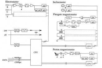
Fig.1 Block diagram of VenusOBEM.

Fig.2 General view of dry-dock test site.
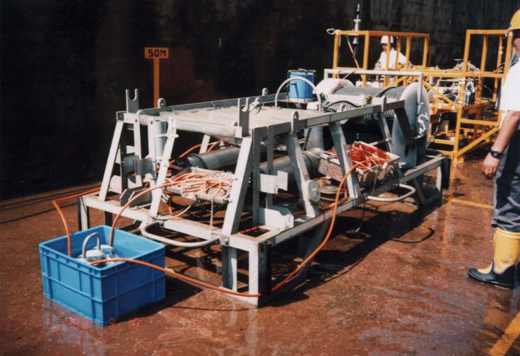
Fig.3 VenusOBEM at dry-dock site in 1998.
Tree electrodes are put in one tub for test operation.

Fig.4 Dry-dock test in 1999.
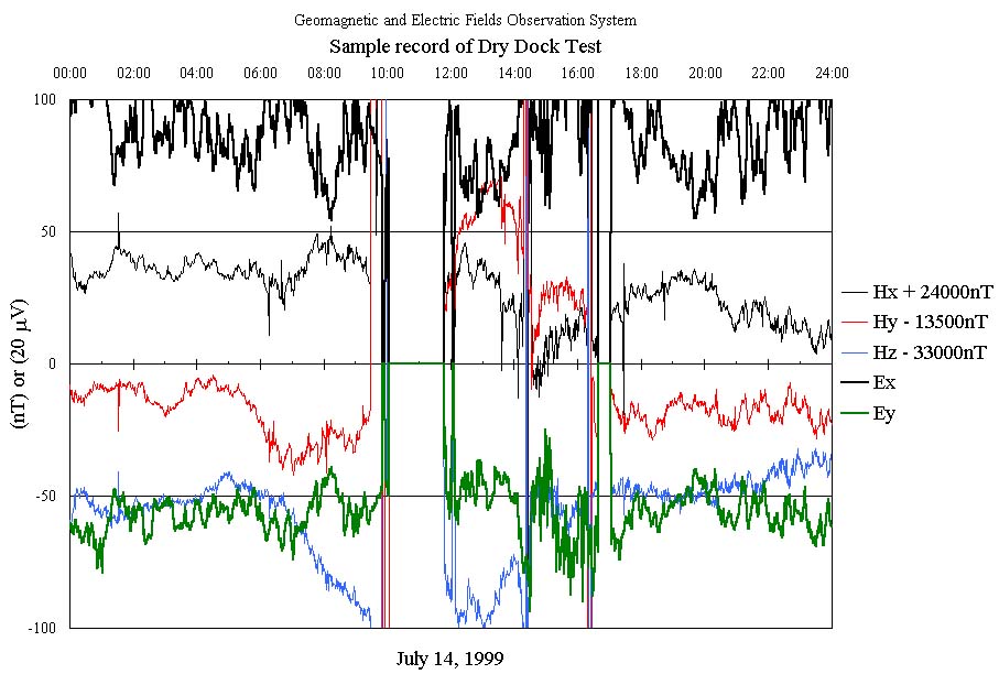
Fig.5 Sample record of dry-dock test in 1999.
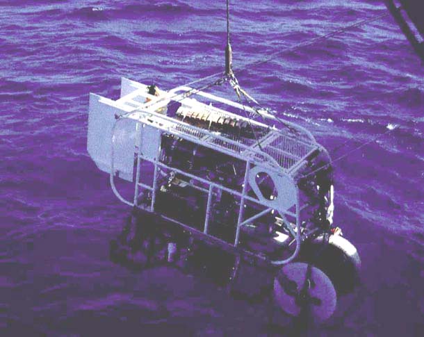
Fig.10 Deep-Tow with VenusOBEM going into sea water. (Sep.22, 1999)
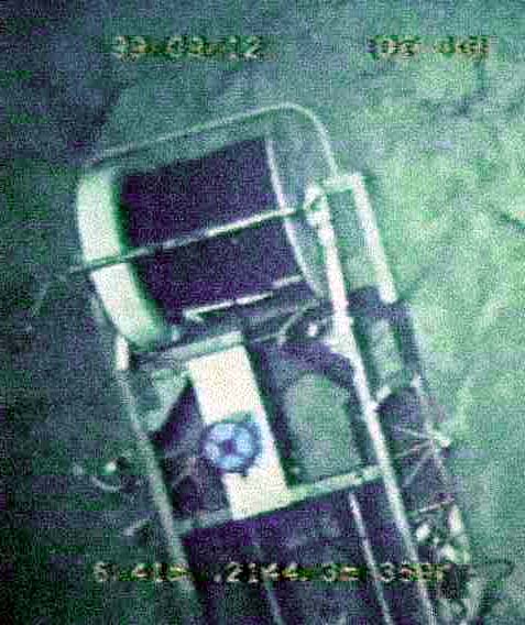
Fig.11 Equipment (VenusOBEM) soon after landing.
(Vertical video image taken from Deep-To frame)
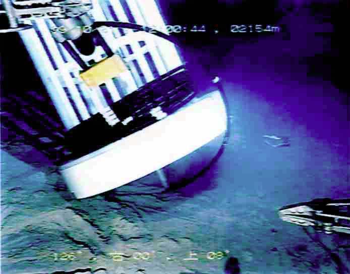
Fig.6 Cable drum (reel) was not stable enough because of too light weight after unrolling the cable.
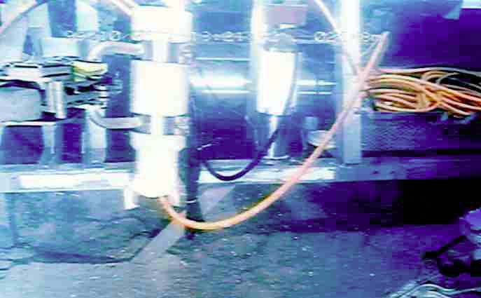
Fig.7 Electrodes were pulled out using the manipulator of ROV.
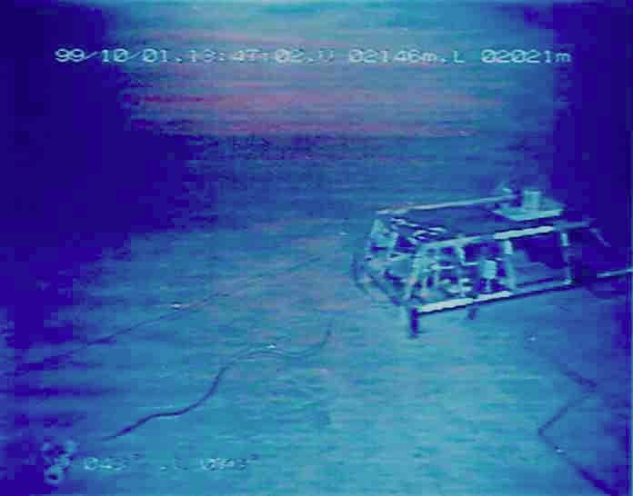
Fig.8 Cables were stretched to get the span between electrodes.
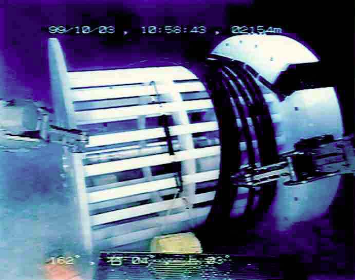
Fig.12 Cable Drum was stabilized using "S" hooks and lead weights, in another dive.
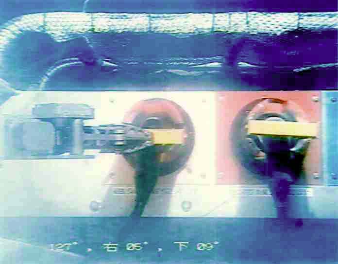
Fig.9 Connection with Branching Unit.